Analytical Services
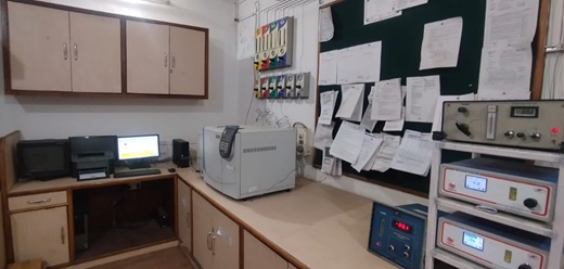
Our Laboratory is equipped with high resolution instruments like gas Chromatographs and other analysers, with wide range of detectors and chromatographic columns to facilitate quantification and certification of components with least uncertainties. The carrier gases used for insrrtuments are of highest purity We can do testing and certification of gas samples at our laboratory by using our gas standards. We can also do revalidation of supplied gas mixtures whose stability period is getting expired.
Gas system Designing for laboratory
In almost any laboratory or research and scientific facility, there are numerous devices, instruments, or processes that require gases to run the instrumentation or process or to calibrate the devices. Gas cylinders that are located in the laboratory area can present significant hazards, and the space they take up can be better used for other more appropriate purposes. Gas delivery systems that are properly designed, sized, and located can improve safety in the laboratory. In addition, attention to high-purity requirements—purity, compatibility, flow, materials of construction, and more—is vital for safety, performance, and cost-efficiency. There are a number of codes and standards that apply to the storage, use, and installation of gases and their delivery systems
Gas Requirement Audit
The first step in properly designing any gas installation, whether it is for a new facility or a retrofit, is to conduct an audit or survey of the gases required for each location or laboratory. Identifying what gases are required for each instrument, their purity level, required delivery pressure, and peak flow demand is essential in determining everything from the size of the piping required, to the storage area required, and even the mode or source in which the gas may be supplied. Overestimating the pressure or flow requirements can result in higher installation costs and reduced gas savings resulting from residual contents left in cylinders or higher monthly rental fees on cylinders that are not required. Underestimating, however, can cause inefficient supply of gas to critical instruments or systems that impair their use or operation.
Selecting a Location for Storage and Gas Delivery Systems
There are some very specific storage and separation requirements for the areas in which compressed or cryogenic gases are stored and/or connected to a building’s gas delivery system. As a minimum, gas cylinders should be stored and secured in an upright position using brackets, chains, or straps in a well-lit and ventilated area away from combustible materials and sources of heat or ignition.
Pipe Sizing and Flow Considerations
When determining what size pipe or tubing to use for a specific application, the main consideration is to determine what the maximum required flow for that specific gas would be if all application or use points were flowing to their maximum at the same time. This can be found by totalling the individual use points and applying a conservative safety factor to allow for growth of requirements of at least 20–50%, depending on what the future outlook is for that gas
Choosing the Right Gas Delivery System
For almost all laboratory gases, maintaining gas purity is a critical requirement. To that end, the choice of materials of construction and their compatibility with that specific gas and its purity level must be considered. It is not enough that the materials are compatible with the specific gas, but that the design ensures and retains the purity of the gas. From the inlet to the outlet, a system that is designed with either bar stock brass or 316L stainless steel components is desired over forged components. Any diaphragms should be made of 316L stainless steel, and the diaphragm seals should be of a metal-to-metal design. Though there are many other areas that must be considered, the primary areas of concern are where to locate the gas storage area outside the laboratory, how much gas will be required, and how the gas will be delivered to the end use points. Users who follow these guidelines are well on their way to selecting a safe and cost-effective gas delivery system.
Cylinder Hydro Testing Shop
What is cylinder hydrotesting?
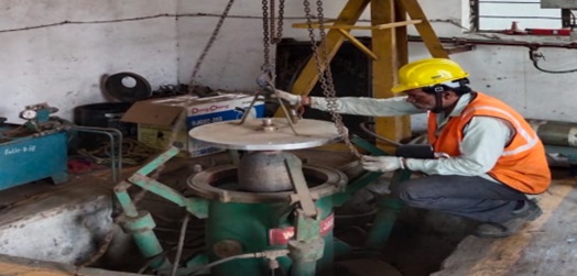
Hydrostatic Testing is a nondestructive test procedure used to check cylinders for leaks, structural flaws, durability, and corrosion. It is used to check a cylinder’s structural integrity. Testing consists of enclosing a cylinder filled with water inside a test jacket filled with water. Pressure is then applied internally to the cylinder, causing the cylinder to expand. The total and permanent volumetric expansions of the cylinder are determined by measuring the amount of water displaced by the expansion of the cylinder when under pressure and after the pressure has been released. An external and internal visual inspection of the cylinder is also performed, along with a dead-ring test for steel cylinders. We are reputed practitioners of cylinder hydro testing, also known as a hydrostatic stretch test, which refers to testing all gas cylinders. However, due to specific reasons, we don’t test the disposable gas bottles and cylinders of acetylene, carbon dioxide, liquid hydrocarbons and welded gas cylinders regardless of cylinder MOC. We encourage regular hydro testing of all other cylinders to ensure that they are in proper working condition and can be used for future purposes. Hydrotesting is only performed under specific procedures and can’t monitor the equipment for leakage. Though hydrostatic testing is a non-destructive testing procedure, the equipment tends to rupture or fail should the inspection exceed a certain test pressure or if cylinder walls develop tiny cracks. We at Alchemie gases & Chemicals pvt Ltd. Offers hydrostatic testing of below specified cylinders which are manufactured as per the standards prescribed by CCOE, petroleum & Explosive safety organisation, ( Government of India) Co2 fire extinguisher, 1 lit to 68 lit
Why is cylinder hydro testing important?
According to the guidelines of The Petroleum and Explosives Safety Organisation (PESO), every gas manufacturing company must perform regular hydro-testing procedures on high-pressure seamless cylinders after every five years. They can undertake this examination at any time of the cylinder’s lifecycle, depending upon their existing condition. Toxic gas and CNG gas cylinders should be regularly hydro-tested every two years or at an interval specified by the PESO. A cylinder is hydraulically tested at the “test pressure”, which could be 1.5 or 1.66 times the normal working pressure. Of course, the amount depends upon the cylinder’s manufacturing standards and MOC. Regular hydro testing is performed to evaluate the cylinder material’s elasticity as it undergoes elastic expansion or stress during the gas filling process. The elasticity must be checked to see the material has returned to its original position within a specific tolerance limit. With repetition and time, its elasticity deteriorates, making it unsafe for further use.
How is hydro-testing performed ?
Hydrotesting refers to a pressure test where the worker fills the container with water, removes the air contained within the unit and pressurizes the system for up to 1.5 times the designed pressure limit of the unit. The worker retains the pressure for a certain amount of time to inspect the system visually for leakage. This is further enhanced by applying fluorescent dyes or tracers to the liquid to check for new leakages and cracks. Three hydrostatic testing methods are used to test small pressure cylinders and vessels:. Water jacket method - The worker fills the cylinder with water and loads it into a sealed chamber (the test jacket), also filled with water. Next, the vessel is pressurized inside the test jacket, which causes the vessel to expand and causes the water to force itself into the glass tube that measures the total expansion. Once recorded, the worker depressurizes the vessel, and the water flows back into the test jacket. If the vessel doesn’t return to its original size, the second size value is renamed permanent expansion. The worker determines the difference between permanent and total expansion, and the vessel is decommissioned if the value is higher. Proof pressure method- The worker causes internal pressure on the vessels to check for wall thinning, leakage or defects. Pneumatic testing involves the worker pressuring the vessel with nitrogen or air instead of water, which must be carefully performed as gaseous mediums can be compressed in large amounts compared to hydro testing. Cylinder hydro testing results are measured in terms of the Percentage Permanent Expansion and must fall within limits prescribed by the PESO. Hydro tests for pipelines are conducted out-of-service pipelines, natural gas or oil is turned off, and the line is cleaned before testing. Reach out to us at Alchemie Gases & Chemicals to meet your requirement.
Training In Gas Handling
We provide a wide range of safety training workshops and courses to support the safety needs of your business and employees. Our training courses include safety in gas cylinder handling and best practices to be used at workplace.
This training will include following points:

Industries
We are serving all industries such as Automotive Industry, Pharmaceuticals, Cement Industries, 4. Fertilizers, Food & Beverages, Hospitals, Instrumentation, Laser gas, Lighting Industries, Metal Manufacturing & Fabrication, Petrochemical & Refineries (Oil & Gas), Research / Laboratories
PURE GASES CGA SELECTION CHART FOR FITTINGS
It is recommended that the user thoroughly familiarize himself with the specific properties of these gases. The Compressed Gas Association (CGA) has selected and standardized the valve outlet to be used on each gas cylinder. These standards, contained in the document “CGA STANDARD V-1, Compressed Gas Cylinder Valve Outlet Connections” , have been adopted to prevent the inadvertent mixing of gases which could be reactive and to avoid other possible misuse hazards. The above chart may be used for guide purposes only. Consult your gas supplier to determine the actual CGA connection required when ordering a regulator.
| CGA Fittings Required | Pure Gases |
|---|---|
| 510/300 | Acetylene |
| 510/300 | Acetylene | 590/346/347/702 | Air |
| 240/660/705 | Ammonia | 580/680/677 | Argon |
| 350 | Arsine* | 320 | Carbon Dioxide |
| 350 | Carbon Monoxide | 660 | Chlorine |
| 510 | Cyclopropane | 350 | Deuterium |
| 350 | Ethane |
| 350 | Ethylene |
| 510 | Ethylene Oxide |
| 580/680/677 | Helium |
| 350/695/703 | Hydrogen |
| 330 | Hydrogen Chloride |
| 330 | Hydrogen Sulfide |
| 580 | Krypton |
| 350/695/703 | Methane |
| 510 | Methyl Chloride |
| 580/680/677 | Neon |
| 580/680/677 | Nitrogen |
| 326 | Nitrous Oxide |
| 540/577/701 | Oxygen* |
| 350 | Phosphine |
| 510 | Propane |
| 350 | Silane* |
| 668/660 | Sulfur Dioxide |
| 590 | Sulfur Hexaflouride |
| 580/680/677 | Xenon |
MIXED GASES CGA SELECTION CHART FOR FITTINGS
Since the combined characteristics of a mixture of gases often differ from the properties of the separate components, different CGA connections are often required. The CGA has selected and standardized the valve outlets to be used with mixed gases. These standards are described in CGA publication V-7 - “Standard Method for Determining Cylinder Valve Outlet Connections for Industrial Gas Mixtures”. Mixtures which use the same CGA connection as if the minor component were in its pure gas form have not been included for the sake of brevity. The proper fitting for these mix- tures can be determined by looking up the minor component on the chart for pure gases.
| CGA Fittings Required | Mixed Gases | |
|---|---|---|
| Minor Component | Major Component | |
| 240/660/705 | Ammonia | Nitrogen |
| 350 | Butane | Nitrogen |
| 296 | Carbon Dioxide | Oxygen |
| 580 | Carbon Dioxide | Helium or Nitrogen |
| 580 | Carbon Dioxide and/or Nitrogen | Helium |
| 590 | Carbon Monoxide | Air |
| 330 | Chlorine | Nitrogen |
| 350 | Diborane | Argon, Helium, Hydrogen, Nitrogen |
| 580 | Freon-12 | Nitrogen |
| 296 | Helium | Oxygen |
| 350 | Hexane | Nitrogen |
| 350 | Isobutane | Nitrogen |
| 580 | Krypton | Argon |
| 590 | Methane | Air |
| 580 | Moisture | Argon, Helium or Nitrogen |
| 660 | Nitric Oxide | Nitrogen |
| 660 | Nitrogen Dioxide | Air or Nitrogen |
| 590 | Nitrous Oxide | Nitrogen |
| 590 | Oxygen | Nitrogen or Helium |
| 350 | Propane | Nitrogen or Helium |
| 590 | Propane | Air |
| 660 | Sulfur Dioxide | Air or Nitrogen |
| 590 | Sulfur Hexaflouride | Argon, Helium or Nitrogen |
| 350 | Sulfur Hexaflouride | Hydrogen |